AMBER
Setting up SIRAH
Note
SIRAH Force Field is distributed with AMBER and AmberTools official releases.
Required Software
AMBER
Amber and AmberTools (version 16 or later) versions properly installed and running in your computer.
Tip
Download the latest version of Amber and AmberTools and refer to the How to obtain Amber23 section for more details on getting Amber23. In addition, go to the Install Amber page for specific instructions based on your operating system. If you have Amber already installed, it is unnecessary to install AmberTools separately.
VMD
The molecular visualization program VMD, version 1.9.3 or later (freely available download). Check VMD’s Installation guide for more instructions.
Prior knowledge
How to perform a standard atomistic molecular dynamics simulations with AMBER and basic usage of VMD.
Tip
AMBER
If you are not familiar with atomistic molecular dynamics simulations, we strongly recommend you to perform the basic usage tutorials of Amber and AmberTools: 1. Building Systems, 3. Creating Stable Systems and Running MD and 5. Case Studies. For more details and documentation, check Amber23 Manual.
VMD
If you are not familiar with VMD, we strongly recommend you to perform the basic usage tutorial of VMD (Using VMD). For more details and documentation, check VMD User Guide and the official VMD documentation.
Download and Setting up SIRAH
Note
Please report bugs, errors or enhancement requests through Issue Tracker or if you have a question about SIRAH open a New Discussion.
Download SIRAH for Amber and uncompress it into your working directory.
tar -xzvf sirah_x2.3_24-07.amber.tar.gz
If you are using a different version of SIRAH, type:
tar -xzvf sirah_[version].amber.tgz
You will get the folder sirah_[version].amber/ containing the force field definition, SIRAH Tools in the
sirah_[version].amber/tools/ folder, molecular structures to build up systems in sirah_[version].amber/PDB/ and the required material to perform the tutorials in sirah_[version].amber/tutorial/X.X/
Caution
Remember to change X.X to the number that corresponds to the tutorial you are going to do.
Make a new folder for this tutorial in your working directory:
mkdir tutorialX.X; cd tutorialX.X
Create the following symbolic link in the folder tutorialX.X:
ln -s ../sirah_x2.3_24-07.amber sirah.amber
Note
SIRAH Force Field is also distributed with AMBER and AmberTools official releases. To use the native AMBER version of SIRAH, create a symbolic link located in $AMBERHOME:
ln -s $AMBERHOME/dat/SIRAH sirah.amber
Check the AMBER Manual section 3.11.2 for more details.
However, if you want the lastest parameters and implementations strongly advise you to use the developers version of SIRAH from GitHub.
1. DNA molecule in implicit solvent
Note
Please report bugs, errors or enhancement requests through Issue Tracker or if you have a question about SIRAH open a New Discussion.
This tutorial shows how to perform a Coarse Grained (CG) simulation of a double stranded DNA using the Generalized Born model for implicit solvent (GB) and the SIRAH force field. The main references for this tutorial are: Dans et al. (latest parameters are those reported here) and Machado & Pantano. We strongly advise you to read these articles before starting the tutorial.
Important
Check the Setting up SIRAH section for download and set up details before starting this tutorial.
Since this is Tutorial 1, remember to replace X.X and the files corresponding to this tutorial can be found in: sirah_[version].amber/tutorial/1/
Note
If you are not familiar with DNA stuff, we strongly recommend you to first perform the AMBER tutorial on DNA.
1.1. Build CG representations
Map the atomistic structure of a 20-mer DNA to its CG representation:
./sirah.amber/tools/CGCONV/cgconv.pl -i ./sirah.amber/tutorial/1/dna.pdb -o dna_cg.pdb
The input file -i dna.pdb contains all the heavy atoms composing the DNA molecule, while the output -o dna_cg.pdb preserves a few of them.
Please check both PDB structures using VMD:
vmd -m ./sirah.amber/tutorial/1/dna.pdb dna_cg.pdb
Tip
This is the basic usage of the script cgconv.pl, you can learn other capabilities from its help by typing:
./sirah.amber/tools/CGCONV/cgconv.pl -h
From now on it is just normal AMBER stuff!
1.2. Prepare LEaP input
Use a text editor to create the file gensystem.leap including the following lines:
# Load SIRAH force field
addPath ./sirah.amber
source leaprc.sirah

# Load model
dna = loadpdb dna_cg.pdb

# Save Parms
saveAmberParmNetcdf dna dna_cg.prmtop dna_cg.ncrst

# EXIT
quit
1.3. Run LEaP
Run the LEAP application to generate the molecular topology and initial coordinate files:
tleap -f gensystem.leap
Note
Warning messages about long, triangular or square bonds in leap.log file are fine and
expected due to the CG topology.
This should create a topology file dna_cg.prmtop and a coordinate file dna_cg.ncrst.
Use VMD to check how the CG model looks like:
vmd dna_cg.prmtop dna_cg.ncrst -e ./sirah.amber/tools/sirah_vmdtk.tcl
Tip
VMD assigns default radius to unknown atom types, the script sirah_vmdtk.tcl sets the right
ones, according to the CG representation. It also provides a kit of useful selection macros, coloring methods and backmapping utilities.
Use the command sirah_help in the Tcl/Tk console of VMD to access the manual pages. To learn about SIRAH Tools’ capabilities, you can also go to the SIRAH Tools tutorial.
1.4. Run the simulation
Make a new folder for the run:
mkdir -p run; cd run
The folder sirah.amber/tutorial/1/PMEMD.GPU/ contains typical input files for energy minimization
(em_GB.in), equilibration (eq_GB.in) and production (md_GB.in) runs. Please check carefully the input
flags therein.
Tip
Some commonly used flags in AMBER
-i: Input file.-o: Output file.-p: Parameter/topology file.-c: Coordinate file.-r: Restart file.-x: Trajectory file.
Caution
These input files are executed by the GPU implementation of pmemd.cuda. Other available modules are sander or pmemd, which are both CPU implementations of Amber.
Note
You can find example input files for CPU versions of sander and pmemd at folders SANDER/ and PMEMD.CPU/, within sirah.amber/tutorial/1/
Energy Minimization:
pmemd.cuda -O -i ../sirah.amber/tutorial/1/PMEMD.GPU/em_GB.in -p ../dna_cg.prmtop -c ../dna_cg.ncrst -o dna_cg_em.out -r dna_cg_em.ncrst &
Important
In the course of long MD simulations the capping residues may eventually separate, this effect is
called helix fraying. To avoid such behavior is necessary to set Watson-Crick restraints for the capping base pairs of this CG DNA at the end of eq_GB.in and md_GB.in files. Check the files lines that start with &rst.
Warning
If you are using sander, to avoid the helix fraying, you must create a symbolic link to the file dna_cg.RST, which
contains the definition of Watson-Crick restraints for the capping base pairs of this CG DNA:
ln -s ../sirah.amber/tutorial/1/SANDER/dna_cg.RST
The file dna_cg.RST can only be read by sander, pmemd reads a different restrain format.
Equilibration:
pmemd.cuda -O -i ../sirah.amber/tutorial/1/PMEMD.GPU/eq_GB.in -p ../dna_cg.prmtop -c dna_cg_em.ncrst -o dna_cg_eq.out -r dna_cg_eq.ncrst -x dna_cg_eq.nc &
Production (100ns):
pmemd.cuda -O -i ../sirah.amber/tutorial/1/PMEMD.GPU/md_GB.in -p ../dna_cg.prmtop -c dna_cg_eq.ncrst -o dna_cg_md.out -r dna_cg_md.ncrst -x dna_cg_md.nc &
1.5. Visualizing the simulation
Now you can load, visualize and analize the trajectory in VMD:
vmd ../dna_cg.prmtop ../dna_cg.ncrst dna_cg_md.nc -e ../sirah.amber/tools/sirah_vmdtk.tcl
Note
The file sirah_vmdtk.tcl is a Tcl script that is part of SIRAH Tools and contains the macros to properly visualize the coarse-grained structures in VMD. Use the command sirah_help in the Tcl/Tk console of VMD to access the manual pages. To learn about SIRAH Tools’ capabilities, you can also go to the SIRAH Tools tutorial.
2. DNA molecule in explicit solvent
Note
Please report bugs, errors or enhancement requests through Issue Tracker or if you have a question about SIRAH open a New Discussion.
This tutorial shows how to use the SIRAH force field to perform a coarse grained (CG) simulation of a double stranded DNA embedded in explicit solvent (called WatFour, WT4). The main references for this tutorial are: Dans et al. (latest parameters are those reported here) and Machado & Pantano. We strongly advise you to read these articles before starting the tutorial.
Important
Check the Setting up SIRAH section for download and set up details before starting this tutorial.
Since this is Tutorial 2, remember to replace X.X and the files corresponding to this tutorial can be found in: sirah_[version].amber/tutorial/2/
2.1. Build CG representations
Map the atomistic structure of a 20-mer DNA to its CG representation:
./sirah.amber/tools/CGCONV/cgconv.pl -i ./sirah.amber/tutorial/2/dna.pdb -o dna_cg.pdb
The input file -i dna.pdb contains all the heavy atoms composing the DNA molecule, while the output -o dna_cg.pdb preserves a few of them.
Please check both PDB structures using VMD:
vmd -m ./sirah.amber/tutorial/2/dna.pdb dna_cg.pdb
Tip
This is the basic usage of the script cgconv.pl, you can learn other capabilities from its help by typing:
./sirah.amber/tools/CGCONV/cgconv.pl -h
From now on it is just normal AMBER stuff!
2.2. Prepare LEaP input
Use a text editor to create the file gensystem.leap including the following lines:
# Load SIRAH force field
addPath ./sirah.amber
source leaprc.sirah

# Load model
dna = loadpdb dna_cg.pdb

# Info on system charge
charge dna

# Add solvent, counterions and 0.15M NaCl
# Tuned solute-solvent closeness for best hydration
solvateoct dna WT4BOX 20 0.7
addionsrand dna NaW 88 ClW 50

# Save Parms
saveAmberParmNetcdf dna dna_cg.prmtop dna_cg.ncrst

# EXIT
quit
See also
The available electrolyte species in SIRAH force field are: Na⁺ (NaW), K⁺ (KW) and Cl⁻ (ClW) which represent solvated ions in solution. One ion pair (e.g., NaW-ClW) each 34 WT4 molecules results in a salt concentration of ~0.15M (see Appendix for details). Counterions were added according to Machado et al..
2.3. Run LEaP
Run the LEaP application to generate the molecular topology and initial coordinate files:
tleap -f gensystem.leap
Note
Warning messages about long, triangular or square bonds in leap.log file are fine and
expected due to the CG topology of some residues.
This should create a topology file dna_cg.prmtop and a coordinate file dna_cg.ncrst.
Use VMD to check how the CG model looks like:
vmd dna_cg.prmtop dna_cg.ncrst -e ./sirah.amber/tools/sirah_vmdtk.tcl
Tip
VMD assigns default radius to unknown atom types, the script sirah_vmdtk.tcl sets the right
ones, according to the CG representation. It also provides a kit of useful selection macros, coloring methods and backmapping utilities.
Use the command sirah_help in the Tcl/Tk console of VMD to access the manual pages. To learn about SIRAH Tools’ capabilities, you can also go to the SIRAH Tools tutorial.
2.4. Run the simulation
Make a new folder for the run:
mkdir -p run; cd run
The folder sirah.amber/tutorial/2/PMEMD/ contains typical input files for energy minimization
(em_WT4.in), equilibration (eq_WT4.in) and production (md_WT4.in) runs. Please check carefully the input flags therein, in particular the definition of flag chngmask=0 at &ewald section is mandatory.
Tip
Some commonly used flags in AMBER
-i: Input file.-o: Output file.-p: Parameter/topology file.-c: Coordinate file.-r: Restart file.-x: Trajectory file.
Caution
These input files are executed by the GPU implementation of pmemd.cuda. Other available modules are sander or pmemd, which are both CPU implementations of Amber.
Note
You can find example input files for CPU versions of sander and pmemd at folders SANDER/ and PMEMD/, within sirah.amber/tutorial/2/
Energy Minimization:
pmemd.cuda -O -i ../sirah.amber/tutorial/2/PMEMD/em_WT4.in -p ../dna_cg.prmtop -c ../dna_cg.ncrst -o dna_cg_em.out -r dna_cg_em.ncrst &
Important
In the course of long MD simulations the capping residues may eventually separate, this effect is
called helix fraying. To avoid such behavior is necessary to set Watson-Crick restraints for the capping base pairs of this CG DNA at the end of eq_GB.in and md_GB.in files. Check the files lines that start with &rst.
Warning
If you are using sander, to avoid the helix fraying, you must create a symbolic link to the file dna_cg.RST, which
contains the definition of Watson-Crick restraints for the capping base pairs of this CG DNA:
ln -s ../sirah.amber/tutorial/1/SANDER/dna_cg.RST
The file dna_cg.RST can only be read by sander, pmemd reads a different restrain format.
Equilibration (NPT):
pmemd.cuda -O -i ../sirah.amber/tutorial/2/PMEMD/eq_WT4.in -p ../dna_cg.prmtop -c dna_cg_em.ncrst -ref dna_cg_em.ncrst -o dna_cg_eq.out -r dna_cg_eq.ncrst -x dna_cg_eq.nc &
Production (100ns):
pmemd.cuda -O -i ../sirah.amber/tutorial/2/PMEMD/md_WT4.in -p ../dna_cg.prmtop -c dna_cg_eq.ncrst -o dna_cg_md.out -r dna_cg_md.ncrst -x dna_cg_md.nc &
2.5. Visualizing the simulation
That’s it! Now you can analyze the trajectory. First, process the output trajectory to account for the Periodic Boundary Conditions (PBC):
echo -e "autoimage\ngo\nquit\n" | cpptraj -p ../dna_cg.prmtop -y dna_cg_md.nc -x dna_cg_md_pbc.nc --interactive
Then, load the processed trajectory in VMD:
vmd ../dna_cg.prmtop ../dna_cg.ncrst dna_cg_md.nc -e ../sirah.amber/tools/sirah_vmdtk.tcl
Note
The file sirah_vmdtk.tcl is a Tcl script that is part of SIRAH Tools and contains the macros to properly visualize the coarse-grained structures in VMD. Use the command sirah_help in the Tcl/Tk console of VMD to access the manual pages. To learn about SIRAH Tools’ capabilities, you can also go to the SIRAH Tools tutorial.
3. Multiscale simulation in implicit solvent
Note
Please report bugs, errors or enhancement requests through Issue Tracker or if you have a question about SIRAH open a New Discussion.
This tutorial shows how to apply a multiscale representation of DNA, which is available in the SIRAH force field, to study protein-DNA interactions. In this approach, the protein and its binding region are treated with an atomistic force field, while the contextual DNA is represented at coarse-grained (CG) level. The simulated system is composed of the human TATA binding protein (TBP PDB: 1C9B) bounded to the TATA box at the promoter region (-64 to +13) of the Human Immunodeficiency Virus type 1 (HIV-1, GenBank: K03455, Figure 1). Solvent effects are considered implicitly using the Generalized Born model (GB).
The main references for this tutorial are: Machado et al. and Machado & Pantano. We strongly advise you to read these articles before starting the tutorial.

Figure 1. Promoter region of HIV-1. The TATA box is highlighted in orange, while base pairs at 0.7nm of TBP are colored in yellow.
Important
Check the Setting up SIRAH section for download and set up details before starting this tutorial.
Since this is Tutorial 3, remember to replace X.X and the files corresponding to this tutorial can be found in: sirah_[version].amber/tutorial/3/
3.1. Build CG representations
Map only the atomistic structure of nucleotides outside the TATA box of the HIV-1 promoter to CG:
./sirah.amber/tools/CGCONV/cgconv.pl -i ./sirah.amber/tutorial/3/tbphiv.pdb -R 1-32,45-110,123-154 -o dna_hyb.pdb
The input file -i tbphiv.pdb contains all the heavy atoms composing the protein-DNA system. Mapped
residues are selected through option -R. The selection considers a “buffer region” of two base pairs at each
side of the TATA box (Figure 1). The atomistic/CG interface must always be a step of B form DNA. The
resulting coordinates are saved in the output -o dna_hyb.pdb.
Please check both PDB structures in VMD:
vmd -m ./sirah.amber/tutorial/3/tbphiv.pdb dna_hyb.pdb
Tip
This is the basic usage of the script cgconv.pl, you can learn other capabilities from its help by typing:
./sirah.amber/tools/CGCONV/cgconv.pl -h
From now on it is just normal AMBER stuff!
3.2. Prepare LEaP input
Use a text editor to create the file gensystem.leap including the following lines:
# Load AMBER force field (parm14SB/parmbsc0)
source oldff/leaprc.ff14SB

# Load SIRAH force field
addPath ./sirah.amber
source leaprc.sirah

# Load model
dna = loadpdb dna_hyb.pdb

# Save Parms
saveAmberParmNetcdf dna dna_hyb.prmtop dna_hyb.ncrst

# EXIT
quit
Note
According to AMBER version 10, 11 or 12 (14) the source file for parm99SB/bsc0 is leaprc.ff99bsc0, leaprc.ff10 or leaprc.ff12SB respectively.
The newest force field version for DNA, bsc1, works equally well with SIRAH.
3.3. Run LEaP
Run the LEaP application to generate the molecular topology and initial coordinate files:
tleap -f gensystem.leap
Note
Warning messages about long, triangular or square bonds in leap.log file are fine and
expected due to the CG topology of some residues.
This should create a topology file dna_hyb.prmtop and a coordinate file dna_hyb.ncrst.
Use VMD to check how the multiscale model looks like:
vmd dna_hyb.prmtop dna_hyb.ncrst -e ./sirah.amber/tools/sirah_vmdtk.tcl
Tip
VMD assigns default radius to unknown atom types, the script sirah_vmdtk.tcl sets the right
ones, according to the CG representation. It also provides a kit of useful selection macros, coloring methods and backmapping utilities.
Use the command sirah_help in the Tcl/Tk console of VMD to access the manual pages. To learn about SIRAH Tools’ capabilities, you can also go to the SIRAH Tools tutorial.
3.4. Run the simulation
Make a new folder for the run:
mkdir -p run; cd run
The folder sirah.amber/tutorial/3/PMEMD.GPU/ contains typical input files for energy minimization
(em_HYB.in), equilibration (eq_HYB.in) and production (md_HYB.in) runs. Please check carefully the input flags therein.
Tip
Some commonly used flags in AMBER
-i: Input file.-o: Output file.-p: Parameter/topology file.-c: Coordinate file.-r: Restart file.-x: Trajectory file.
Caution
These input files are executed by the GPU implementation of pmemd.cuda. Other available modules are sander or pmemd, which are both CPU implementations of Amber.
Note
You can find example input files for CPU versions of sander and pmemd at folders SANDER/ and PMEMD.CPU/, within sirah.amber/tutorial/3/
However, this simulation is time consuming owing to the system’s size. A parallel or CUDA implementation of Amber is advised.
Energy Minimization:
pmemd.cuda -O -i ../sirah.amber/tutorial/3/PMEMD.GPU/em_HYB.in -p ../dna_hyb.prmtop -c ../dna_hyb.ncrst -o dna_hyb_em.out -r dna_hyb_em.ncrst &
Important
In the course of long MD simulations the capping residues may eventually separate, this effect is
called helix fraying. To avoid such behavior is necessary to set Watson-Crick restraints for the capping base pairs of this CG DNA at the end of eq_GB.in and md_GB.in files. Check the files lines that start with &rst.
Warning
If you are using sander, to avoid the helix fraying, you must create a symbolic link to the file dna_cg.RST, which
contains the definition of Watson-Crick restraints for the capping base pairs of this CG DNA:
ln -s ../sirah.amber/tutorial/3/SANDER/dna_hyb.RST
The file dna_cg.RST can only be read by sander, pmemd reads a different restrain format.
Equilibration:
pmemd.cuda -O -i ../sirah.amber/tutorial/3/PMEMD.GPU/eq_HYB.in -p ../dna_hyb.prmtop -c dna_hyb_em.ncrst -o dna_hyb_eq.out -r dna_hyb_eq.ncrst -x dna_hyb_eq.nc &
Production (10ns):
pmemd.cuda -O -i ../sirah.amber/tutorial/3/PMEMD.GPU/md_HYB.in -p ../dna_hyb.prmtop -c dna_hyb_eq.ncrst -o dna_hyb_md.out -r dna_hyb_md.ncrst -x dna_hyb_md.nc &
3.5. Visualizing the simulation
That’s it! Now you can load, visualize and analize the trajectory file in VMD:
vmd ../dna_hyb.prmtop ../dna_hyb.ncrst dna_hyb_md.nc -e ../sirah.amber/tools/sirah_vmdtk.tcl
Note
The file sirah_vmdtk.tcl is a Tcl script that is part of SIRAH Tools and contains the macros to properly visualize the coarse-grained structures in VMD. Use the command sirah_help in the Tcl/Tk console of VMD to access the manual pages. To learn about SIRAH Tools’ capabilities, you can also go to the SIRAH Tools tutorial.
4. Closed circular DNA in implicit solvent
Note
Please report bugs, errors or enhancement requests through Issue Tracker or if you have a question about SIRAH open a New Discussion.
This tutorial shows how to use the SIRAH force field to perform a coarse grained (CG) simulation of a closed circular DNA using the Generalized Born model (GB) for implicit solvent.
The main references for this tutorial are: Dans et al. (latest parameters are those reported here) and Machado & Pantano. We strongly advise you to read these articles before starting the tutorial.
Important
Check the Setting up SIRAH section for download and set up details before starting this tutorial.
Since this is Tutorial 4, remember to replace X.X and the files corresponding to this tutorial can be found in: sirah_[version].amber/tutorial/4/
4.1. Build CG representations
Map the atomistic structure of the closed circular DNA to its CG representation:
./sirah.amber/tools/CGCONV/cgconv.pl -i ./sirah.amber/tutorial/4/ccdna.pdb | sed -e 's/DCX A 1/CW5 A 1/' -e 's/DCX B 1/CW5 B 1/' -e 's/DGX A 100/GW3 A 100/' -e 's/DGX B 100/GW3 B 100/' > ccdna_cg.pdb
Note
The 5’ and 3’ end residues must be renamed to AW5, TW5, GW5 or CW5 and AW3, TW3, GW3 or CW3 to represent the corresponding Adenine, Thymine, Guanine or Cytosine extremes in a closed circular DNA.
The input file -i ccdna.pdb contains all the heavy atoms composing the DNA molecule, while the output -o ccdna_cg.pdb preserves a few of them.
Tip
This is the basic usage of the script cgconv.pl, you can learn other capabilities from its help by typing:
./sirah.amber/tools/CGCONV/cgconv.pl -h
Please check both PDB structures using VMD:
vmd -m ./sirah.amber/tutorial/4/ccdna.pdb ccdna_cg.pdb
From now on it is just normal AMBER stuff!
4.2. Prepare LEaP input
Use a text editor to create the file gensystem.leap including the following lines:
# Load SIRAH force field
addPath ./sirah.amber
source leaprc.sirah

# Load model
dna = loadpdb ccdna_cg.pdb

# Make a covalently closed circular DNA
bond dna.1.PX dna.100.C1X
bond dna.101.PX dna.200.C1X

# Save Parms
saveAmberParmNetcdf dna ccdna_cg.prmtop ccdna_cg.ncrst

# EXIT
quit
4.3. Run LEaP
Run the LEaP application to generate the molecular topology and initial coordinate files:
tleap -f gensystem.leap
Note
Warning messages about long, triangular or square bonds in leap.log file are fine and
expected due to the CG topology of some residues.
This should create a topology file ccdna_cg.prmtop and a coordinate file ccdna_cg.ncrst.
Use VMD to check how the CG model looks like:
vmd ccdna_cg.prmtop ccdna_cg.ncrst -e ./sirah.amber/tools/sirah_vmdtk.tcl
Tip
VMD assigns default radius to unknown atom types, the script sirah_vmdtk.tcl sets the right
ones, according to the CG representation. It also provides a kit of useful selection macros, coloring methods and backmapping utilities.
Use the command sirah_help in the Tcl/Tk console of VMD to access the manual pages. To learn about SIRAH Tools’ capabilities, you can also go to the SIRAH Tools tutorial.
4.4. Run the simulation
Make a new folder for the run:
mkdir -p run; cd run
The folder sirah.amber/tutorial/4/GPU contains typical input files for energy minimization (em_GBSA.in), equilibration (eq_GBSA.in) and production (md_GBSA.in) runs. Please check carefully the input flags therein.
Tip
Some commonly used flags in AMBER
-i: Input file.-o: Output file.-p: Parameter/topology file.-c: Coordinate file.-r: Restart file.-x: Trajectory file.
Caution
These input files are executed by the GPU implementation of pmemd.cuda. Other available modules are sander or pmemd, which are both CPU implementations of Amber.
Note
You can find example input files for CPU versions of sander and pmemd at folder CPU/, within sirah.amber/tutorial/4/
Energy Minimization:
pmemd.cuda -O -i ../sirah.amber/tutorial/4/GPU/em_GBSA.in -p ../ccdna_cg.prmtop -c ../ccdna_cg.ncrst -o ccdna_cg_em.out -r ccdna_cg_em.ncrst &
Equilibration:
pmemd.cuda -O -i ../sirah.amber/tutorial/4/GPU/eq_GBSA.in -p ../ccdna_cg.prmtop -c ccdna_cg_em.ncrst -o ccdna_cg_eq.out -r ccdna_cg_eq.ncrst -x ccdna_cg_eq.nc &
Production (100ns):
pmemd.cuda -O -i ../sirah.amber/tutorial/4/GPU/md_GBSA.in -p ../ccdna_cg.prmtop -c ccdna_cg_eq.ncrst -o ccdna_cg_md.out -r ccdna_cg_md.ncrst -x ccdna_cg_md.nc &
4.5. Visualizing the simulation
That’s it! Now you can load, visualize and analize the trajectory file in VMD:
vmd ../ccdna_cg.prmtop ../ccdna_cg.ncrst ccdna_cg_md.nc -e ../sirah.amber/tools/sirah_vmdtk.tcl
Note
The file sirah_vmdtk.tcl is a Tcl script that is part of SIRAH Tools and contains the macros to properly visualize the coarse-grained structures in VMD. Use the command sirah_help in the Tcl/Tk console of VMD to access the manual pages. To learn about SIRAH Tools’ capabilities, you can also go to the SIRAH Tools tutorial.
5. Proteins in explicit solvent
Note
Please report bugs, errors or enhancement requests through Issue Tracker or if you have a question about SIRAH open a New Discussion.
This tutorial shows how to use the SIRAH force field to perform a coarse grained (CG) simulation of a protein in explicit solvent (called WatFour, WT4). The main references for this tutorial are: Darré et al., Machado et al. and Machado & Pantano. We strongly advise you to read these articles before starting the tutorial.
Important
Check the Setting up SIRAH section for download and set up details before starting this tutorial.
Since this is Tutorial 5, remember to replace X.X and the files corresponding to this tutorial can be found in: sirah_[version].amber/tutorial/5/
5.1. Build CG representations
Caution
The mapping to CG requires the correct protonation state of each residue at a given pH. We recommend using the CHARMM-GUI server and use the PDB Reader & Manipulator to prepare your system. An account is required to access any of the CHARMM-GUI Input Generator modules, and it can take up to 24 hours to obtain one.
Other option is the PDB2PQR server and choosing the output naming scheme of AMBER for best compatibility. This server was utilized to generate the PQR file featured in this tutorial. Be aware that modified residues lacking parameters such as: MSE (seleno MET), TPO (phosphorylated TYR), SEP (phosphorylated SER) or others are deleted from the PQR file by the server. In that case, mutate the residues to their unmodified form before submitting the structure to the server.
Map the protonated atomistic structure of protein 1CRN to its CG representation:
./sirah.amber/tools/CGCONV/cgconv.pl -i ./sirah.amber/tutorial/5/1CRN.pqr -o 1CRN_cg.pdb
The input file -i 1CRN.pqr contains the atomistic representation of 1CRN structure at pH 7.0, while the output -o 1CRN_cg.pdb is its SIRAH CG representation.
Tip
This is the basic usage of the script cgconv.pl, you can learn other capabilities from its help by typing:
./sirah.amber/tools/CGCONV/cgconv.pl -h
Note
Pay attention to residue names when mapping structures from other atomistic force fields or experimental structures. Although we provide compatibility for naming schemes in PDB, GMX, GROMOS, CHARMM and OPLS, there might always be some ambiguity in the residue naming, specially regarding protonation states, that may lead to a wrong mapping. For example, SIRAH Tools always maps the residue name “HIS” to a Histidine protonated at the epsilon nitrogen (\(N_{\epsilon}\)) regardless the actual proton placement. Similarly, protonated Glutamic and Aspartic acid residues must be named “GLH” and “ASH”, otherwise they will be treated as negative charged residues. In addition, protonated and disulfide bonded Cysteines must be named “CYS” and “CYX” respectively. These kind of situations need to be carefully checked by the users. In all cases the residues preserve their identity when mapping and back-mapping the structures. Hence, the total charge of the protein should be the same at atomistic and SIRAH levels. You can check the following mapping file to be sure of the compatibility: sirah.amber/tools/CGCONV/maps/sirah_prot.map.
Important
By default, charged termini are used, but it is possible to set them neutral by renaming the residues from s[code] to a[code] (Nt-acetylated) or m[code] (Ct-amidated) after mapping to CG, where [code] is the root residue name in SIRAH. For example, to set a neutral N-terminal Histidine protonated at epsilon nitrogen (\(N_{\epsilon}\)) rename it from “sHe” to “aHe”.
Please check both PDB and PQR structures using VMD:
vmd -m sirah.amber/tutorial/5/1CRN.pqr 1CRN_cg.pdb
From now on it is just normal Amber stuff!
5.2. Prepare LEaP input
Use a text editor to create the file gensystem.leap including the following lines:
# Load SIRAH force field
addPath ./sirah.amber
source leaprc.sirah

# Load model
protein = loadpdb 1CRN_cg.pdb

# Info on system charge
charge protein

# Set S-S bridges
bond protein.3.BSG protein.40.BSG
bond protein.4.BSG protein.32.BSG
bond protein.16.BSG protein.26.BSG

# Add solvent, counterions and 0.15M NaCl
# Tuned solute-solvent closeness for best hydration
solvateOct protein WT4BOX 20 0.7
addIonsRand protein NaW 22 ClW 22

# Save Parms
saveAmberParmNetcdf protein 1CRN_cg.prmtop 1CRN_cg.ncrst

# EXIT
quit
Caution
Each disulfide bond must be defined explicitly in LEaP using the command bond, e.g.: “bond unit.ri.BSG unit.rj.BSG”. Where ri and rj correspond to the residue index in the topology file starting from 1, which may differ from the biological sequence in the PDB file. You can try the command pdb4amber to get those indexes from the atomistic structure, but be aware that it may not work if the Cysteine residues are too far away:
pdb4amber -i sirah.amber/tutorial/5/1CRN.pqr -o 1CRN_aa.pdb && cat 1CRN_aa_sslink
See also
The available electrolyte species in SIRAH force field are: Na⁺ (NaW), K⁺ (KW) and Cl⁻ (ClW) which represent solvated ions in solution. One ion pair (e.g., NaW-ClW) each 34 WT4 molecules results in a salt concentration of ~0.15M (see Appendix for details). Counterions were added according to Machado et al..
5.3. Run LEaP
Run the LEaP application to generate the molecular topology and initial coordinate files:
tleap -f gensystem.leap
Note
Warning messages about long, triangular or square bonds in leap.log file are fine and expected due to the CG topology of some residues.
This should create a topology file 1CRN_cg.prmtop and a coordinate file 1CRN_cg.ncrst.
Use VMD to check how the CG model looks like and particularly the presence of disulfide bonds:
vmd 1CRN_cg.prmtop 1CRN_cg.ncrst -e ./sirah.amber/tools/sirah_vmdtk.tcl
Tip
VMD assigns default radius to unknown atom types, the script sirah_vmdtk.tcl sets the right
ones, according to the CG representation. It also provides a kit of useful selection macros, coloring methods and backmapping utilities.
Use the command sirah_help in the Tcl/Tk console of VMD to access the manual pages. To learn about SIRAH Tools’ capabilities, you can also go to the SIRAH Tools tutorial.
5.4. Run the simulation
Make a new folder for the run:
mkdir -p run; cd run
The folder sirah.amber/tutorial/5/ contains typical input files for energy minimization
(em1_WT4.in and em2_WT4.in), equilibration (eq1_WT4.in and eq2_WT4.in) and production (md_WT4.in) runs. Please check carefully the
input flags therein, in particular the definition of flag chngmask=0 at &ewald section is mandatory.
Tip
Some commonly used flags in Amber
-i: Input file.-o: Output file.-p: Parameter/topology file.-c: Coordinate file.-r: Restart file.-x: Trajectory file.-ref: Reference file
Caution
These input files are executed by the GPU implementation of pmemd.cuda. Other available modules are sander or pmemd, which are both CPU implementations of Amber.
Note
The same input files can be used to run on CPU with the modules pmemd or sander.
Energy Minimization of side chains and solvent by restraining the backbone:
pmemd.cuda -O -i ../sirah.amber/tutorial/5/em1_WT4.in -p ../1CRN_cg.prmtop -c ../1CRN_cg.ncrst -ref ../1CRN_cg.ncrst -o 1CRN_cg_em1.out -r 1CRN_cg_em1.ncrst &
Energy Minimization of whole system:
pmemd.cuda -O -i ../sirah.amber/tutorial/5/em2_WT4.in -p ../1CRN_cg.prmtop -c 1CRN_cg_em1.ncrst -o 1CRN_cg_em2.out -r 1CRN_cg_em2.ncrst &
Solvent Equilibration (NPT):
pmemd.cuda -O -i ../sirah.amber/tutorial/5/eq1_WT4.in -p ../1CRN_cg.prmtop -c 1CRN_cg_em2.ncrst -ref 1CRN_cg_em2.ncrst -o 1CRN_cg_eq1.out -r 1CRN_cg_eq1.ncrst -x 1CRN_cg_eq1.nc &
Caution
Option restraintmask=:’1-46’ in input file eq1_WT4.in must be set specifically for each system to embrace all protein’s residues.
Soft equilibration to improve side chain solvation (NPT):
pmemd.cuda -O -i ../sirah.amber/tutorial/5/eq2_WT4.in -p ../1CRN_cg.prmtop -c 1CRN_cg_eq1.ncrst -ref 1CRN_cg_eq1.ncrst -o 1CRN_cg_eq2.out -r 1CRN_cg_eq2.ncrst -x 1CRN_cg_eq2.nc &
Production (1000ns):
pmemd.cuda -O -i ../sirah.amber/tutorial/5/md_WT4.in -p ../1CRN_cg.prmtop -c 1CRN_cg_eq2.ncrst -o 1CRN_cg_md.out -r 1CRN_cg_md.ncrst -x 1CRN_cg_md.nc &
5.5. Visualizing the simulation
That’s it! Now you can analyze the trajectory. Process the output trajectory to account for the Periodic Boundary Conditions (PBC):
echo -e "autoimage\ngo\nquit\n" | cpptraj -p ../1CRN_cg.prmtop -y 1CRN_cg_md.nc -x 1CRN_cg_md_pbc.nc --interactive
Load the processed trajectory in VMD:
vmd ../1CRN_cg.prmtop ../1CRN_cg.ncrst 1CRN_cg_md.nc -e ../sirah.amber/tools/sirah_vmdtk.tcl
Note
The file sirah_vmdtk.tcl is a Tcl script that is part of SIRAH Tools and contains the macros to properly visualize the coarse-grained structures in VMD. Use the command sirah_help in the Tcl/Tk console of VMD to access the manual pages. To learn about SIRAH Tools’ capabilities, you can also go to the SIRAH Tools tutorial.
6. Lipid bilayers in explicit solvent
Note
Please report bugs, errors or enhancement requests through Issue Tracker or if you have a question about SIRAH open a New Discussion.
This tutorial shows how to use the SIRAH force field to perform a coarse grained (CG) simulation of a DMPC bilayer in explicit solvent (called WatFour, WT4). The main references for this tutorial are: Barrera et al. and Machado & Pantano. We strongly advise you to read these articles before starting the tutorial. You may also find interesting this book chapter.
Note
If you are not familiar with membrane stuff we strongly recommend you to first perform the Amber tutorial on lipids.
Important
Check the Setting up SIRAH section for download and set up details before starting this tutorial.
Since this is Tutorial 6, remember to replace X.X and the files corresponding to this tutorial can be found in: sirah_[version].amber/tutorial/6/
6.1. Build CG representations
Map the atomistic structure of the preassembled DMPC bilayer to its CG representation:
./sirah.amber/tools/CGCONV/cgconv.pl -i ./sirah.amber/tutorial/6/DMPC64.pdb -o DMPC64_cg.pdb -a sirah.amber/tools/CGCONV/maps/tieleman_lipid.map
The input file -i DMPC64.pdb contains the atomistic representation of the DMPC bilayer, while the output -o DMPC64_cg.pdb is its SIRAH CG representation. The flag -a is a mapping scheme for lipids.
Important
By default, no mapping is applied to lipids, as there is no standard naming convention for them. So users are requested to append a MAP file from the list in Table 1, by setting the flag -a in cgconv.pl. We recommend using PACKMOL for building the system. Reference building-block structures are provided at folder sirah.amber/PDB/, which agree with the mapping scheme in sirah.amber/tools/CGCONV/maps/tieleman_lipid.map. The provided DMPC bilayer contains 64 lipid molecules per leaflet distributed in a 6.4 * 6.4 nm surface, taking into account an approximate area per lipid of 0.64 nm2 at 333 K. The starting configuration was created with the input file sirah.amber/tutorial/6/DMPC_bilayer.pkm. See FAQs for cautions on mapping lipids to SIRAH and tips on using fragment-based topologies. If you do not find your issue please start a discussion in our github discussion page F&Q.
Tip
This an advanced usage of the script cgconv.pl, you can learn other capabilities from its help by typing:
./sirah.amber/tools/CGCONV/cgconv.pl -h
The input file DMPC64.pdb contains all the heavy atoms composing the lipids, while the output DMPC64_cg.pdb preserves a few of them. Please check both PDB structures using VMD:
vmd -m sirah.amber/tutorial/6/DMPC64.pdb DMPC64_cg.pdb
From now on it is just normal Amber stuff!
6.2. Prepare LEaP input
Use a text editor to create the file gensystem.leap including the following lines:
# Load SIRAH force field
addPath ./sirah.amber
source leaprc.sirah

# Load model
Lipid = loadpdb DMPC64_cg.pdb

# Add solvent, counterions and 0.15M NaCl
# Tuned solute-solvent closeness for best hydration
solvateBox Lipid WT4BOX {0 0 40} 0.7
addIonsRand Lipid NaW 33 ClW 33

# Save Parms
saveAmberParmNetcdf Lipid DMPC64_cg.prmtop DMPC64_cg.ncrst

# EXIT
quit
See also
The available electrolyte species in SIRAH force field are: Na⁺ (NaW), K⁺ (KW) and Cl⁻ (ClW) which represent solvated ions in solution. One ion pair (e.g., NaW-ClW) each 34 WT4 molecules results in a salt concentration of ~0.15M (see Appendix for details). Counterions were added according to Machado et al..
6.3. Run LEaP
Run the LEaP application to generate the molecular topology and initial coordinate files:
tleap -f gensystem.leap
Note
Warning messages about long, triangular or square bonds in leap.log file are fine and expected due to the CG topology.
This should create a topology file DMPC64_cg.prmtop and a coordinate file DMPC64_cg.ncrst.
Use VMD to check how the CG model looks:
vmd DMPC64_cg.prmtop DMPC64_cg.ncrst -e ./sirah.amber/tools/sirah_vmdtk.tcl
By selecting +X, +Y and +Z periodic images from the Periodic tab in the Graphical Representations window you will see small vacuum slices at box boundaries. In the following step we will fix this issue by reducing the box dimensions a few angstroms. See FAQs for issues on membrane systems in Amber.
Tip
VMD assigns default radius to unknown atom types, the script sirah_vmdtk.tcl sets the right
ones, according to the CG representation. It also provides a kit of useful selection macros, coloring methods and backmapping utilities.
Use the command sirah_help in the Tcl/Tk console of VMD to access the manual pages. To learn about SIRAH Tools’ capabilities, you can also go to the SIRAH Tools tutorial.
6.4. Resize the box with CPPTRAJ
Note
As PACKMOL does not consider periodicity while building up the system, increasing the XY box sides a few Angstroms may be required to avoid bad contacts between images.
Use a text editor to create the file resize_box.cpptraj including the following lines:
# New box dimensions
box x 66 y 66 z 132

# Amber NetCDF Restart generation
trajout DMPC64_cg_nb.ncrst

# Do it!
go

# EXIT
quit
Run the CPPTRAJ application to adjust the size of the simulation box:
cpptraj -p DMPC64_cg.prmtop -y DMPC64_cg.ncrst -i resize_box.cpptraj
Once again, use VMD to check the PBC images in the new box of the system:
vmd DMPC64_cg.prmtop DMPC64_cg_nb.ncrst -e ./sirah.amber/tools/sirah_vmdtk.tcl
6.5. Run the simulation
Make a new folder for the run:
mkdir -p run; cd run
The folder sirah.amber/tutorial/6/ contains typical input files for energy minimization
(em_Lipid.in), heating (heat_Lipid.in), equilibration (eq_Lipid.in) and production (md_Lipid.in) runs. Please check carefully the input flags.
Tip
Some commonly used flags in AMBER
-i: Input file.-o: Output file.-p: Parameter/topology file.-c: Coordinate file.-r: Restart file.-x: Trajectory file.-ref: Reference file
Warning
These input files are executed by the GPU implementation of pmemd.cuda. Other available modules are sander or pmemd, which are both CPU implementations of Amber.
However, this simulation is time consuming owing to the system’s size. A parallel or CUDA implementation of Amber is advised.
Energy Minimization:
pmemd.cuda -O -i ../sirah.amber/tutorial/6/em_Lipid.in -p ../DMPC64_cg.prmtop -c ../DMPC64_cg_nb.ncrst -o DMPC64_cg_em.out -r DMPC64_cg_em.ncrst &
Heating:
pmemd.cuda -O -i ../sirah.amber/tutorial/6/heat_Lipid.in -p ../DMPC64_cg.prmtop -c DMPC64_cg_em.ncrst -o DMPC64_cg_eq_0.out -r DMPC64_cg_eq_0.ncrst -x DMPC64_cg_eq_0.nc &
Important
To avoid “skinnb errors” on GPU due to large box size fluctuations, the system must be equilibrated by several “short” runs using a large skinnb value. The number and length of the runs may vary according to the characteristic stabilization times of the system. For more information visit the Amber tutorial on lipids.
Periodic box equilibration in GPU code (500 ps x 9):
for i in $(seq 1 9)
do
        echo "running equilibration $i"
        pmemd.cuda -O \
        -i ../sirah.amber/tutorial/6/eq_Lipid.in \
        -p ../DMPC64_cg.prmtop \
        -c DMPC64_cg_eq_$(($i -1)).ncrst \
        -o DMPC64_cg_eq_$i.out \
        -r DMPC64_cg_eq_$i.ncrst \
        -x DMPC64_cg_eq_$i.nc
done &
Production (1000ns):
pmemd.cuda -O -i ../sirah.amber/tutorial/6/md_Lipid.in -p ../DMPC64_cg.prmtop -c DMPC64_cg_eq_9.ncrst -o DMPC64_cg_md.out -r DMPC64_cg_md.ncrst -x DMPC64_cg_md.nc &
6.6. Visualizing the simulation
That’s it! Now you can analyze the trajectory.
Process the output trajectory to account for the Periodic Boundary Conditions (PBC):
echo -e "autoimage\ngo\nquit\n" | cpptraj -p ../DMPC64_cg.prmtop -y DMPC64_cg_md.nc -x DMPC64_cg_md_pbc.nc --interactive
Now you can check the simulation using VMD:
vmd ../DMPC64_cg.prmtop DMPC64_cg_md_pbc.nc -e ../sirah.amber/tools/sirah_vmdtk.tcl
Note
The file sirah_vmdtk.tcl is a Tcl script that is part of SIRAH Tools and contains the macros to properly visualize the coarse-grained structures in VMD. Use the command sirah_help in the Tcl/Tk console of VMD to access the manual pages. To learn about SIRAH Tools’ capabilities, you can also go to the SIRAH Tools tutorial.
You can also use CPPTRAJ to calculate the area per lipid:
cpptraj -p ../DMPC64_cg.prmtop -i ../sirah.amber/tutorial/6/area_lipid.cpptraj
Use Grace to plot the results:
xmgrace apl_DMPC64_310K.dat
Note
To calculate the area per lipid, divide the membrane’s area by the DMPC molecules per leaflet:
\[\frac{Area}{Lipid} = \frac{Box(x) * Box(y)}{64}\]
And density profiles and bilayer thickness:
cpptraj -p ../DMPC64_cg.prmtop -i ../sirah.amber/tutorial/6/dens_profile.cpptraj
Use Grace to plot the results:
xmgrace -nxy dens_profile_DMPC64_310K.dat
Note
The thickness of the bilayer is the distance between the two peaks corresponding to the position of phosphate beads (BFO) along the z-axis.
7. Membrane proteins in explicit solvent
Note
Please report bugs, errors or enhancement requests through Issue Tracker or if you have a question about SIRAH open a New Discussion.
This tutorial shows how to use the SIRAH force field to perform a coarse grained (CG) simulation of a protein embedded in a lipid bilayer using explicit solvent (called WatFour, WT4). The main references for this tutorial are: Machado et al., Barrera et al., and Machado & Pantano. We strongly advise you to read these articles before starting the tutorial.
Note
We strongly advise you to read and complete Tutorial 5 and Tutorial 6 before starting.
Important
Check the Setting up SIRAH section for download and set up details before starting this tutorial.
Since this is Tutorial 7, remember to replace X.X and the files corresponding to this tutorial can be found in: sirah_[version].amber/tutorial/7/
7.1. Build CG representations
Caution
The mapping to CG requires the correct protonation state of each residue at a given pH. We recommend using the CHARMM-GUI server and use the PDB Reader & Manipulator to prepare your system. An account is required to access any of the CHARMM-GUI Input Generator modules, and it can take up to 24 hours to obtain one.
See Tutorial 5 for cautions while preparing and mapping atomistic proteins to SIRAH.
Map the atomistic structure of protein 2KYV to its CG representation:
./sirah.amber/tools/CGCONV/cgconv.pl -i sirah.amber/tutorial/7/2kyv.pqr -o 2kyv_cg.pdb
The input file -i 2kyv.pqr contains the atomistic representation of 2KYV structure at pH 7.0, while the output -o 2kyv_cg.pdb is its SIRAH CG representation.
Important
If you already have an atomistic protein within a membrane, then you can simply map the entire system to SIRAH (this is highly recommended) and skip the step 2, however clipping the membrane patch may be required to set a correct solvation box (see bellow). By default, no mapping is applied to lipids, as there is no standard naming convention for them. So users are requested to append a MAP file from the list in Table 1, by setting the flag -a in cgconv.pl. We recommend using PACKMOL for building the system. Reference building-block structures are provided at folder sirah.amber/PDB/, which agree with the mapping scheme sirah.amber/tools/CGCONV/maps/tieleman_lipid.map. See FAQs for cautions on mapping lipids to SIRAH and tips on using fragment-based topologies.
Tip
This an advanced usage of the script cgconv.pl, you can learn other capabilities from its help by typing:
./sirah.amber/tools/CGCONV/cgconv.pl -h
7.1.1. Embed the protein in a lipid bilayer
We will show one possible way to do it by starting from a pre-equilibrated CG membrane patch.
In sirah_[version].amber/tutorial/7/ you will find a pre-stabilized CG DMPC bilayer patch, concatenate it with the previously generated CG representation of the phospholamban (PLN) pentamer (PDB code: 2KYV):
head -qn -1 2kyv_cg.pdb ./sirah.amber/tutorial/7/DMPC_cg.pdb > 2kyv_DMPC_cg_init.pdb
Luckily, we already oriented the protein inside the membrane. For setting up your own system you can go to Orientations of Proteins in Membranes (OPM) database and (if your structure is available) use the dummy atoms provided there to make them match with your membrane model (see Figure 1).
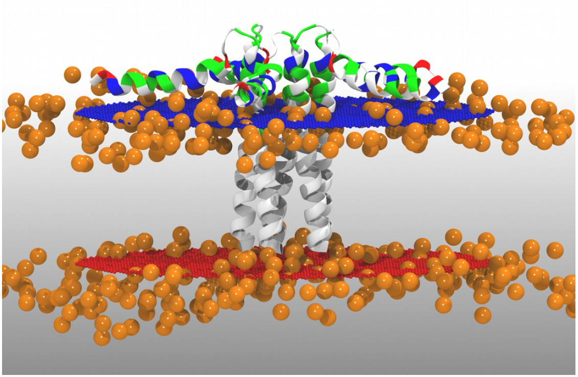
Figure 1. Protein oriented inside the membrane from the OPM database with dummy atoms represented as orange spheres.
7.1.2. Delete close contact lipid molecules
We need to use VMD to to delete lipid molecules in close contact with the protein. For a proper treatment and visualization of the system in VMD you must first generate the molecular topology and initial coordinate files.
Use a text editor to create the file geninit.leap including the following lines:
# Load SIRAH force field
addPath ./sirah.amber
source leaprc.sirah

# Load model
ProtMem = loadpdb 2kyv_DMPC_cg_init.pdb

# Save Parms
saveAmberParmNetcdf ProtMem 2kyv_DMPC_cg_init.prmtop 2kyv_DMPC_cg_init.ncrst

# EXIT
quit
Run the LEaP application to generate the molecular topology and initial coordinate files:
tleap -f geninit.leap
Note
Warning messages about long, triangular or square bonds in leap.log file are fine and expected due to the CG topology.
Now, open the files on VMD:
vmd 2kyv_DMPC_cg_init.prmtop 2kyv_DMPC_cg_init.ncrst -e sirah.amber/tools/sirah_vmdtk.tcl
Tip
VMD assigns default radius to unknown atom types, the script sirah_vmdtk.tcl sets the right
ones, according to the CG representation. It also provides a kit of useful selection macros, coloring methods and backmapping utilities.
Use the command sirah_help in the Tcl/Tk console of VMD to access the manual pages. To learn about SIRAH Tools’ capabilities, you can also go to the SIRAH Tools tutorial.
In the VMD main window, select Graphics > Representations. In the Selected Atoms box, type:
not (same residue as (sirah_membrane within 3.5 of sirah_protein) or (sirah_membrane and x < 5 or x > 142 or y < 2 or y > 140))
Important
In the first part of the selection, lipid molecules in close contact with the protein are removed. The second one is made to “trim” the membrane patch, deleting lipids with acyl chains located in the periodic boundary images. This is frequent when using pre-equilibrated membrane patches and is necessary to avoid clashes in the following steps.
To save the refined protein-membrane system, in the VMD main window click on 2kyv_DMPC_cg_init.prmtop, then select File > Save Coordinates. In the Selected atoms option choose the selection you have just created and Save as 2kyv_DMPC_cg.pdb.
From now on it is just normal AMBER stuff!
7.2. Prepare LEaP input
Use a text editor to create the file gensystem.leap including the following lines:
# Load SIRAH force field
addPath ./sirah.amber
source leaprc.sirah

# Load model
ProtMem = loadpdb 2kyv_DMPC_cg.pdb

# Info on system charge
charge ProtMem

# Prevent adding solvent molecules beyond the membrane boundaries
setbox ProtMem centers 0

# Add solvent, counterions and 0.15M NaCl
# Tuned solute-solvent closeness for best hydration
solvateBox ProtMem WT4BOX {0,0,27} 0.7
addIonsRand ProtMem NaW 109 ClW 124

# Save Parms
saveAmberParmNetcdf ProtMem 2kyv_DMPC_cg.prmtop 2kyv_DMPC_cg.ncrst

# EXIT
quit
See also
The available electrolyte species in SIRAH force field are: Na⁺ (NaW), K⁺ (KW) and Cl⁻ (ClW) which represent solvated ions in solution. One ion pair (e.g., NaW-ClW) each 34 WT4 molecules results in a salt concentration of ~0.15M (see Appendix for details). Counterions were added according to Machado et al..
7.3. Run LEaP
Run the LEaP application to generate the molecular topology and initial coordinate files:
tleap -f gensystem.leap
Caution
Warning messages about long, triangular or square bonds in leap.log file are fine and expected due to the CG topology.
This should create a topology file 2kyv_DMPC_cg.prmtop and a coordinate file 2kyv_DMPC_cg.ncrst.
Use VMD to check how the CG model looks:
vmd 2kyv_DMPC_cg.prmtop 2kyv_DMPC_cg.ncrst -e ./sirah.amber/tools/sirah_vmdtk.tcl
By selecting +X, +Y and +Z periodic images from the Periodic tab in the Graphical Representations window you will see unwanted water near the hydrophobic region of the membrane and small vacuum slices at box boundaries. In the following step we will fix these issues by deleting those water molecules and reducing the box dimensions a few angstroms. See FAQs for issues on membrane systems in Amber. If you do not find your issue please start a discussion in our github discussion page F&Q.
7.4. Resize the box with CPPTRAJ
Note
As PACKMOL does not consider periodicity while building up the system, increasing the XY box sides a few Angstroms may be required to avoid bad contacts between images.
Use a text editor to create the file resize_box.cpptraj including the following lines:
# Set reference coordinate file
reference 2kyv_DMPC_cg.ncrst

# Remove water using distance-based masks
strip :WT4&(@BCT1,BCT2,BC13,BC23<:12.0) parmout 2kyv_DMPC_cg.prmtop

# New box dimensions
box x 128 y 128 z 114

# Amber NetCDF Restart generation
trajout 2kyv_DMPC_cg_nb.ncrst

# Do it!
 go

# EXIT
 quit
Caution
This is a critical step when preparing membrane systems to simulate with Amber. In this case, the new box dimensions were set after some trial and error tests to allow for limited overlap between periodic box images. An excessive overlap may lead to important atom clashes an eventual system explosion during minimization/simulation, while insufficient overlap may impact the membrane cohesivity at PBC boundaries leading to pore formations or other issues.
Run the CPPTRAJ application application to adjust the size of the simulation box:
cpptraj -p 2kyv_DMPC_cg.prmtop -y 2kyv_DMPC_cg.ncrst -i resize_box.cpptraj
Once again, use VMD to check the PBC images in the new box of the system:
vmd 2kyv_DMPC_cg.prmtop 2kyv_DMPC_cg_nb.ncrst -e ./sirah.amber/tools/sirah_vmdtk.tcl
7.5. Run the simulation
Make a new folder for the run:
mkdir -p run; cd run
The folder sirah.amber/tutorial/7/ contains typical input files for energy minimization
(em1_Prot-Lip.in and em2_Prot-Lip.in), heating (heat_Prot-Lip.in), equilibration (eq_Prot-Lip.in) and production (md_Prot-Lip.in) runs. Please check carefully the input flags.
Tip
Some commonly used flags in Amber
-i: Input file.-o: Output file.-p: Parameter/topology file.-c: Coordinate file.-r: Restart file.-x: Trajectory file.-ref: Reference file
Warning
These input files are executed by the GPU implementation of pmemd.cuda. Other available modules are sander or pmemd, which are both CPU implementations of Amber.
However, this simulation is time consuming owing to the system’s size. A parallel or CUDA implementation of Amber is advised.
Energy Minimization of side chains by restraining the backbone:
pmemd.cuda -O -i ../sirah.amber/tutorial/7/em1_Prot-Lip.in -p ../2kyv_DMPC_cg.prmtop -c ../2kyv_DMPC_cg_nb.ncrst -ref ../2kyv_DMPC_cg_nb.ncrst -o 2kyv_DMPC_cg_em_1.out -r 2kyv_DMPC_cg_em_1.ncrst &
Energy Minimization of of the whole system:
pmemd.cuda -O -i ../sirah.amber/tutorial/7/em2_Prot-Lip.in -p ../2kyv_DMPC_cg.prmtop -c 2kyv_DMPC_cg_em_1.ncrst -ref 2kyv_DMPC_cg_em_1.ncrst -o 2kyv_DMPC_cg_em_2.out -r 2kyv_DMPC_cg_em_2.ncrst &
Heating:
pmemd.cuda -O -i ../sirah.amber/tutorial/7/heat_Prot-Lip.in -p ../2kyv_DMPC_cg.prmtop -c 2kyv_DMPC_cg_em_2.ncrst -ref 2kyv_DMPC_cg_em_2.ncrst -o 2kyv_DMPC_cg_eq_0.out -r 2kyv_DMPC_cg_eq_0.ncrst -x 2kyv_DMPC_cg_eq_0.nc &
Important
To avoid “skinnb errors” on GPU due to large box size fluctuations, the system must be equilibrated by several “short” runs using a large skinnb value. The number and length of the runs may vary according to the characteristic stabilization times of the system. For more information visit the Amber tutorial on lipids.
Periodic box equilibration in GPU code (500 ps x 9):
for i in $(seq 1 9)
do
        echo "running equilibration $i"
        pmemd.cuda -O \
        -i ../sirah.amber/tutorial/7/heat_Prot-Lip.in \
        -p ../2kyv_DMPC_cg.prmtop \
        -c 2kyv_DMPC_cg_eq_$(($i -1)).ncrst \
        -ref 2kyv_DMPC_cg_eq_$(($i -1)).ncrst \
        -o 2kyv_DMPC_cg_eq_$i.out \
        -r 2kyv_DMPC_cg_eq_$i.ncrst \
        -x 2kyv_DMPC_cg_eq_$i.nc
done &
Production (1000ns):
pmemd.cuda -O -i ../sirah.amber/tutorial/7/md_Prot-Lip.in -p ../2kyv_DMPC_cg.prmtop -c 2kyv_DMPC_cg_eq_9.ncrst -o 2kyv_DMPC_cg_md.out -r 2kyv_DMPC_cg_md.ncrst -x 2kyv_DMPC_cg_md.nc &
7.6. Visualizing the simulation
That’s it! Now you can analyze the trajectory.
Process the output trajectory to account for the Periodic Boundary Conditions (PBC):
echo -e "autoimage\ngo\nquit\n" | cpptraj -p ../2kyv_DMPC_cg.prmtop -y 2kyv_DMPC_cg_md.nc -x 2kyv_DMPC_cg_md_pbc.nc --interactive
Now you can check the simulation using VMD:
vmd ../2kyv_DMPC_cg.prmtop 2kyv_DMPC_cg_md_pbc.nc -e ../sirah.amber/tools/sirah_vmdtk.tcl
Note
The file sirah_vmdtk.tcl is a Tcl script that is part of SIRAH Tools and contains the macros to properly visualize the coarse-grained structures in VMD. Use the command sirah_help in the Tcl/Tk console of VMD to access the manual pages. To learn about SIRAH Tools’ capabilities, you can also go to the SIRAH Tools tutorial.
8. Glycoprotein in explicit solvent
Note
Please report bugs, errors or enhancement requests through Issue Tracker or if you have a question about SIRAH open a New Discussion.
This tutorial shows how to use the SIRAH force field to perform a coarse grained (CG) simulation of a glycoprotein in explicit solvent (called WatFour, WT4). The main references for this tutorial are: Darré et al., Machado et al. and Machado & Pantano. We strongly advise you to read these articles before starting the tutorial.
Important
Check the Setting up SIRAH section for download and set up details before starting this tutorial.
Since this is Tutorial 8, remember to replace X.X and the files corresponding to this tutorial can be found in: sirah_[version].amber/tutorial/8/
8.1. Build CG representations
Caution
The mapping to CG requires the correct protonation state of each residue at a given pH. We recommend using the CHARMM-GUI server with the Glycan Reader & Modeler to prepare your system, choosing the output naming scheme of AMBER for best compatibility. An account is required to access any of the CHARMM-GUI Input Generator modules, and it can take up to 24 hours to obtain one.
This example use the structure of glycoprotein 1GYA, using CHARMM-GUI server are obtained the files parm7 and rst7, these files are converted to pdb format with the naming scheme of AMBER/GLYCAM using AmberTool as follow:
ambpdb -p ./sirah.amber/tutorial/8/step3_input.parm7 -c ./sirah.amber/tutorial/8/step3_input.rst7 > 1GYA_glycam.pdb
From the file 1GYA_glycam.pdb generated delete the solvent, rename to 1GYA_glycam_NoW.pdb and then map the protonated atomistic structure to its CG representation:
./sirah.amber/tools/CGCONV/cgconv.pl -i ./sirah.amber/tutorial/8/1GYA_glycam_NoW.pdb -o 1GYA_cg.pdb
The input file -i 1GYA_glycam_NoW.pdb contains the atomistic representation of 1GYA structure at pH 7.0, while the output -o 1GYA_cg.pdb is its SIRAH CG representation.
Tip
This is the basic usage of the script cgconv.pl, you can learn other capabilities from its help by typing:
./sirah.amber/tools/CGCONV/cgconv.pl -h
Note
Pay attention to residue names when mapping structures from other atomistic force fields or experimental structures. Although we provide compatibility for naming schemes in PDB, GMX, GROMOS, CHARMM and OPLS, there might always be some ambiguity in the residue naming, specially regarding protonation states, that may lead to a wrong mapping. For example, SIRAH Tools always maps the residue name “HIS” to a Histidine protonated at the epsilon nitrogen (\(N_{\epsilon}\)) regardless the actual proton placement. Similarly, protonated Glutamic and Aspartic acid residues must be named “GLH” and “ASH”, otherwise they will be treated as negative charged residues. In addition, protonated and disulfide bonded Cysteines must be named “CYS” and “CYX” respectively. These kind of situations need to be carefully checked by the users. In all cases the residues preserve their identity when mapping and back-mapping the structures. Hence, the total charge of the protein should be the same at atomistic and SIRAH levels. You can check the following mapping file to be sure of the compatibility: sirah.amber/tools/CGCONV/maps/sirah_prot.map and sirah_glycans.map.
Important
By default, charged termini are used. However, it is possible to set them neutral by renaming the residues from s[code] to a[code] (Nt-acetylated) or m[code] (Ct-amidated) after mapping to CG, where [code] is the root residue name in SIRAH. For example, to set a neutral N-terminal Histidine protonated at epsilon nitrogen (\(N_{\epsilon}\)) rename it from “sHe” to “aHe”.
Please check both PDBs structures using VMD:
vmd -m sirah.amber/tutorial/8/1GYA_glycam_NoW.pdb 1GYA_cg.pdb
From now on it is just normal Amber stuff!
8.2. Prepare LEaP input
Use a text editor to create the file gensystem.leap including the following lines:
# Load SIRAH force field
addPath ./sirah.amber
source leaprc.sirah

# Load model
glycoprot = loadpdb 1GYA_cg.pdb

charge glycoprot

# N-Glycosilation
bond glycoprot.111.GO2  glycoprot.110.GO2
bond glycoprot.110.GO2  glycoprot.109.GO6

bond glycoprot.112.GO2  glycoprot.109.GO3
bond glycoprot.109.GO2  glycoprot.108.GO6

bond glycoprot.114.GO2 glycoprot.113.GO2
bond glycoprot.113.GO2 glycoprot.108.GO3

bond glycoprot.108.GO2  glycoprot.107.GO4
bond glycoprot.107.GNac glycoprot.106.GO4
# ASN 65
bond glycoprot.106.GNac glycoprot.65.BND


# Add solvent, counterions and 0.15M NaCl
# Tuned solute-solvent closeness for best hydration
solvateOct glycoprot WT4BOX 20 0.7
addIonsRand glycoprot NaW 40 ClW 41

# Save topology
saveAmberParmNetcdf glycoprot 1GYA_cg.prmtop 1GYA_cg.ncrst

# EXIT
quit
Caution
Each glycosidic bond must be defined explicitly in LEaP using the command bond, e.g.: “bond unit.ri.beadi unit.rj.beadj”. Where ri and rj correspond to the residue index in the topology file starting from 1, which may differ from the biological sequence in the PDB file. And beadi and beadj are the names of the beads involved in the glycosidic bond of the corresponding residues.
The above also applies to each disulfide bond, e.g.: “bond unit.ri.BSG unit.rj.BSG”. You can try the command pdb4amber to get those indexes from the atomistic structure, but be aware that it may not work if the Cysteine residues are too far away (in this case result in an empty file):
pdb4amber -i sirah.amber/tutorial/8/1GYA_glycam_NoW.pdb -o 1GYA_aa.pdb && cat 1GYA_aa_sslink
See also
The available electrolyte species in SIRAH force field are: Na⁺ (NaW), K⁺ (KW) and Cl⁻ (ClW) which represent solvated ions in solution. One ion pair (e.g., NaW-ClW) each 34 WT4 molecules results in a salt concentration of ~0.15M (see Appendix for details). Counterions were added according to Machado et al..
8.3. Run LEaP
Run the LEaP application to generate the molecular topology and initial coordinate files:
tleap -f gensystem.leap
Note
Warning messages about long, triangular or square bonds in leap.log file are fine and expected due to the CG topology of some residues.
This should create a topology file 1GYA_cg.prmtop and a coordinate file 1GYA_cg.ncrst.
Use VMD to check how the CG model looks like and particularly the presence of glycosidic bonds:
vmd 1GYA_cg.prmtop 1GYA_cg.ncrst -e ./sirah.amber/tools/sirah_vmdtk.tcl
Tip
VMD assigns default radius to unknown atom types, the script sirah_vmdtk.tcl sets the right
ones, according to the CG representation. It also provides a kit of useful selection macros, coloring methods and backmapping utilities.
Use the command sirah_help in the Tcl/Tk console of VMD to access the manual pages. To learn about SIRAH Tools’ capabilities, you can also go to the SIRAH Tools tutorial.
8.4. Run the simulation
Make a new folder for the run:
mkdir -p run; cd run
The folder sirah.amber/tutorial/8/ contains typical input files for energy minimization
(em1_WT4.in and em2_WT4.in), relaxation (or equilibration) (eq1_WT4.in and eq2_WT4.in) and production (md_WT4.in) runs. Please check carefully the
input flags therein, in particular the definition of flag chngmask=0 at &ewald section is mandatory.
Tip
Some commonly used flags in Amber
-i: Input file.-o: Output file.-p: Parameter/topology file.-c: Coordinate file.-r: Restart file.-x: Trajectory file.-ref: Reference file
Caution
These input files are executed by the GPU implementation of pmemd.cuda. Other available modules are sander or pmemd, which are both CPU implementations of Amber.
Note
The same input files can be used to run on CPU with the modules pmemd or sander.
Energy Minimization of side chains and solvent by restraining the protein backbone and glycan rings:
pmemd.cuda -O -i ../sirah.amber/tutorial/8/em1_WT4.in -p ../1GYA_cg.prmtop -c ../1GYA_cg.ncrst -ref ../1GYA_cg.ncrst -o 1GYA_cg_em1.out -r 1GYA_cg_em1.ncrst &
Energy Minimization of whole system:
pmemd.cuda -O -i ../sirah.amber/tutorial/8/em2_WT4.in -p ../1GYA_cg.prmtop -c ../1GYA_cg_em1.ncrst -o 1GYA_cg_em2.out -r 1GYA_cg_em2.ncrst &
Solvent Relaxation (or equlibration) in NPT:
pmemd.cuda -O -i ../sirah.amber/tutorial/8/eq1_WT4.in -p ../1GYA_cg.prmtop -c 1GYA_cg_em2.ncrst -ref 1GYA_cg_em2.ncrst -o 1GYA_cg_eq1.out -r 1GYA_cg_eq1.ncrst -x 1GYA_cg_eq1.nc &
Caution
Option restraintmask=:’1-114’ in input file eq1_WT4.in must be set specifically for each system to restrain all glycoprotein’s residues.
Soft Relaxation to improve side chain and glycan solvation (NPT):
pmemd.cuda -O -i ../sirah.amber/tutorial/8/eq2_WT4.in -p ../1GYA_cg.prmtop -c 1GYA_cg_eq1.ncrst -ref 1GYA_cg_eq1.ncrst -o 1GYA_cg_eq2.out -r 1GYA_cg_eq2.ncrst -x 1GYA_cg_eq2.nc &
Production (1000ns):
pmemd.cuda -O -i ../sirah.amber/tutorial/8/md_WT4.in -p ../1GYA_cg.prmtop -c 1GYA_cg_eq2.ncrst -o 1GYA_cg_md.out -r 1GYA_cg_md.ncrst -x 1GYA_cg_md.nc &
8.5. Visualizing the simulation
That’s it! Now you can analyze the trajectory. Process the output trajectory to account for the Periodic Boundary Conditions (PBC):
echo -e "autoimage\ngo\nquit\n" | cpptraj -p ../1GYA_cg.prmtop -y 1GYA_cg_md.nc -x 1GYA_cg_md_pbc.nc --interactive
Load the processed trajectory in VMD:
vmd ../1GYA_cg.prmtop ../1GYA_cg.ncrst 1GYA_cg_md.nc -e ../sirah.amber/tools/sirah_vmdtk.tcl
Note
The file sirah_vmdtk.tcl is a Tcl script that is part of SIRAH Tools and contains the macros to properly visualize the coarse-grained structures in VMD. Use the command sirah_help in the Tcl/Tk console of VMD to access the manual pages. To learn about SIRAH Tools’ capabilities, you can also go to the SIRAH Tools tutorial.
9. Non-enveloped Viral-Like Particle
Caution
This tutorial was developed for the Workshop and Course on Molecular, Physical, and Computational Virology. Please be aware that the scripts and commands given here might not work right on your system due to software versions diferences.
This tutorial shows how to use the SIRAH force field to perform a coarse grained (CG) simulation of a non-enveloped Virus-like Particle (VLP) in explicit solvent (called WatFour, WT4). The main references for this tutorial are: Darré et al., Machado et al., Machado et al. and Soñora et al.. We strongly advise you to read these articles before starting the tutorial.
Important
Check the Setting up SIRAH section for download and set up details before starting this tutorial.
Since this is Tutorial 9, remember to replace X.X and the files corresponding to this tutorial can be found in: sirah_[version].amber/tutorial/9/
Warning
This tutorial uses tools like Packmol and PDB2PQR that are not part of the AmberTools suite. You can find the latest version of Packmol here. You can install PDB2PQR locally by:
conda install conda-forge::pdb2pqr
9.1. Structure preprocessing
Note
This tutorial provides the necessary steps to assemble viral particles for SIRAH CG simulation. However, it is crucial to address any potential errors in the PDB files before proceeding. These preprocessing steps can prevent issues related to incorrect atom labeling, missing residues, clashes, or other common artifacts that are present in raw PDB data. View Prof. Jodi Hadden-Perilla’s fantastic video on Tips and Tricks for MD Simulation of Viruses for more details.
9.1.1 Working with the Biological Assembly of an entire VLP
Important
In this tutorial, we will use a Biological Assembly from the PDB to work with an already-assembled Porcine Circovirus 2 (PCV2) VLP. In 9.1.3, we demonstrate how to generate a VLP of a non-enveloped virus from its asymmetric unit if your system is not already assembled.
The PCV2 6OLA structure, which includes the VLP and genomic DNA fragments in its inner core, is used in this tutorial. Download the Biological Assembly from the PDB, making sure you are in the sirah.amber/tutorial/9/ folder:
wget https://files.rcsb.org/download/6OLA-assembly1.cif.gz
Decompress the Biological Assembly:
gzip -d 6OLA-assembly1.cif.gz
Open the cif file with VMD:
vmd 6OLA-assembly1.cif
After loading the structure, we must saved it in PDB format by going to File > Save Coordinates > Selected Atoms > all option. Enter File type as pdb and hit Save. Assign filename as 6ola_assembly.pdb and click OK.
You can close VMD now.
Some structures may have structural issues or artifacts that affect their preparation or simulation. Thus, it is crucial to check the details of the structure and its integrity prior to any step.
Regarding the 6OLA structure, there are three critical issues that require correction:
Issue 1. The structure contains 60 DNA fragments and each DNA fragment includes a phosphate atom from the subsequent nucleotide. However, this nucleotide was not modeled; only the phosphate was included. Thus, when we attempt to generate the topology using LEaP, the process is stopped since it fails to reconstruct a nucleotide that is absent. This should be corrected by removing the extra phosphate and oxigen atoms. We can correct this using the following command:
sed '/\(P[[:space:]]\+1DC[[:space:]]\+[A-Z][[:space:]]\+1\|OP11DC[[:space:]]\+[A-Z][[:space:]]\+1\|OP21DC[[:space:]]\+[A-Z][[:space:]]\+1\)/d' 6ola_assembly.pdb > 6ola_modified_1.pdb
This line of code creates a new PDB file by removing the lines containing the P, OP1, and OP2 atoms from the original structure.
Issue 2. Another issue is the incorrect assignment of residue names according to their protonation state. Following AMBER force field rules, histidine residue name can vary depending on whether the protonation occurs at the delta nitrogen (HID), epsilon nitrogen (HIE), or if the residue is doubly protonated (HIP). Different residue names can also be given to ASP (ASH), GLU (GLH), and CYS (CYM or CYX if they are part of a disulfide bond).
In order to comply with AMBER force field rules, the PDB file must be edited to update residues protonations. To achieve this, we will first inspect the PDB structure in VMD to identify the relevant protonations.
Note
In this part of the tutorial, we established the protonation states using the proton locations as provided in the original Biological Assembly of 6OLA structure.
Open VMD:
vmd 6ola_modified_1.pdb
Once in VMD, let’s examine one of the fragments (or protomers) of the PCV2 capsid. To do this, go to the Graphics tab and select Representations. In the Graphics Representations menu, go to Selected Atoms and make the selection of histidines from fragment 0 using the following selection command:
resname HIS and fragment 0
You should run this command again and check the protons position for all the other protonable residues, such as ASP, GLU, and CYS.
Important
The only residues in this structure that appear to have distinct protonation states are the three histidines. Use your mouse to navigate and identify which nitrogens are protonated to correctly adjust their residue’s names. Following proton location, HIS 113 is protonated at the epsilon nitrogen (\(N_{\epsilon}\)), HIS 122 is protonated at the delta nitrogen (\(N_{\delta}\)), and HIS 160 is protonated at the epsilon nitrogen (\(N_{\epsilon}\)).
Close VMD. Use the command below to modify the names of the histidine’s residues:
sed -e '/HIS[[:space:]]\+[A-Z][[:space:]]113/s/HIS/HIE/' -e '/HIS[[:space:]]\+[A-Z][[:space:]]122/s/HIS/HID/' -e '/HIS[[:space:]]\+[A-Z][[:space:]]160/s/HIS/HIE/' 6ola_modified_1.pdb > 6ola_modified_2.pdb
Issue 3. Another important step for this structure is to correct the atom index numbers, ensuring they range from 0 to 99999. Additionally, a TER record should be added at the end of each chain, and an END record should be included at the end of the structure.
To do this, we can use the fixpdb.tcl VMD script found in the sirah.amber/tutorial/9/ folder:
vmd -dispdev text 6ola_modified_2.pdb -e ./sirah.amber/tutorial/9/fixpdb.tcl
Then
mv 6ola_modified_2_final.pdb 6ola_modified_final.pdb
If all stages were completed successfully, the final PDB file 6ola_modified_final.pdb is generated.
Issue 4 (Issue 2 - Alternative). Instead of assigning protonation states by hand, you can use tools that take into account the surrounding residues and the pH conditions to do it automatically. You can use servers, like the CHARMM-GUI server and PDB2PQR server. The
6ola_modified_final.pdbshould work without any issues, though it may take a while to execute.
Tip
An additional approach to circumvent potential server execution issues is to submit a minimal fragment of your symmetrized VLP that includes all of the interfaces between subunits as input.
Caution
The mapping to CG requires the correct protonation state of each residue at a given pH. We recommend using the CHARMM-GUI server and use the PDB Reader & Manipulator to prepare your system. An account is required to access any of the CHARMM-GUI Input Generator modules, and it can take up to 24 hours to obtain one.
Other option is the PDB2PQR server and choosing the output naming scheme of AMBER for best compatibility. This server was utilized to generate the PQR file featured in this tutorial. Be aware that modified residues lacking parameters such as: MSE (seleno MET), TPO (phosphorylated TYR), SEP (phosphorylated SER) or others are deleted from the PQR file by the server. In that case, mutate the residues to their unmodified form before submitting the structure to the server.
Given the scale and complexity of the system, using the pdb2pqr script to perform the calculations locally is one method to get around potential server problems. Therefore, we can assign protonation states using pH ~ 7.0 with the following command:
pdb2pqr --ff=AMBER --keep-chain --ffout=AMBER --titration-state-method=propka --with-ph=7.0 --include-header ./6ola_modified_final.pdb ./6ola_modified_final.pqr
A PQR file 6ola_modified_final.pqr is generated containing protonation state of each residue at the given pH.
9.1.2 Calculate system charge
Note
As a result of the system’s size and the various methods available for assigning hydrogen atoms, the most straightforward method of verifying the current charge of the VLP is to calculate the number of charged amino acids and phosphate atoms within the system.
To do this, we can use the CountCharge.sh script found in the sirah.amber/tutorial/9/ folder by:
./sirah.amber/tutorial/9/CountCharge.sh 6ola_modified_final.pdb
This script evaluates the number of positively and negatively charged residues in the system and provides the net charge that can be used in later steps of preparing the VLP for simulations.
Tip
The file CountCharge.sh was made for this system, we suggest that you inspect the file to gain a more comprehensive understanding of the script and then change it to work with your own system.
+--------------------+----------+
|      Molecule      | Count    |
+====================+==========+
| LYS (CA)           |  540     |
| ARG (CA)           | 1020     |
| GLU (CA)           |  240     |
| ASP (CA)           |  720     |
| Phosphate (P)      |  180     |
|--------------------|----------|
|Total Positv Charge | 1560     |
|Total Negatv Charge | 1140     |
|Net Charge          |  420     |
+--------------------|----------+
9.1.3 Packing the assimetric unit to build an entire VLP (Alternative)
Caution
This step should be performed only when the input file (.pdb or .cif) is the asymmetric unit. For more details about asymetric unit and biological assemblies, check the RCSB PDB website.
In complex systems like viruses, some biological assemblies are constructed from the asymmetric unit, which in virology may be represented by a single protein or a small number of them, referred to as a capsomer or protomer. In these cases, it is essential to assemble the whole VLP by employing symmetry operations (rotations and translations) with the symmetry matrices included in the original PDB file. Thus, based on the available structure, it may be necessary to initially assemble the entire VLP.
In sirah.amber/tutorial/9/example_3JCI you will find the asymmetric unit of the capsid protein of the PCV2 (PDB code: 3JCI) along with the necessary files to assemble its VLP.
The first step to assemble a VLP is to minimize the protomer. To do this, we need to create a 3JCI.leap file to generate the molecular topology and initial coordinate files:
# Load AMBER force field
source leaprc.protein.ff14SB

# Load model
pcv2 = loadPdb 3jci.pdb

# Save Parms
saveamberparm pcv2 3JCI_aa.prmtop 3JCI_aa.inpcrd

# EXIT
quit
Run the LEaP application with:
tleap -f 3JCI.leap
Make a new folder to run the minimization:
mkdir -p run; cd run
Run the minimization with sander:
mpirun -np 4 sander.MPI -O -i ../em_cpu.in -p ../3JCI_aa.prmtop -c ../3JCI_aa.inpcrd -ref ../3JCI_aa.inpcrd -inf mdinfo -o 3JCI_aa_em.out -r 3JCI_aa_em.rst7 &
Note
The same input file can be used to run on CPU with the modules pmemd, sander or sander.MPI. Or the GPU implementation, pmemd.cuda.
Once the protomer has been minimized, return to the original folder:
cd ..
And build the VLP using the capsid.tcl VMD script:
vmd -dispdev text -e ./sirah.amber/tutorial/9/capsid.tcl
Note
Due to its complexity, we suggest that you inspect the capsid.tcl file to gain a more comprehensive understanding of the procedure.
That’s it! You can now use VMD to see what the VLP looks like:
vmd PCV2_capsid_OK.pdb
9.2. Build CG representations
Caution
We are using the 6ola_modified_final.pdb file for this section of the tutorial, which makes use of the assigned protonation states and hydrogen atoms as given in the original Biological Assembly VLP. But you may also use the automatically calculated protonation states file 6ola_modified_final.pqr.
Map the atomistic structure of VLP that was prepared in the previous step to its CG representation:
./sirah.amber/tools/CGCONV/cgconv.pl -i 6ola_modified_final.pdb -o 6ola_modified_final_cg.pdb
The input file -i 6ola_modified_final.pdb has the atomistic model of the VLP that has had its structure issues fixed,, while the output -o 6ola_modified_final_cg.pdb is its SIRAH CG representation.
Tip
This is the basic usage of the script cgconv.pl, you can learn other capabilities from its help by typing:
./sirah.amber/tools/CGCONV/cgconv.pl -h
Note
Pay attention to residue names when mapping structures from other atomistic force fields or experimental structures. Although we provide compatibility for naming schemes in PDB, GMX, GROMOS, CHARMM and OPLS, there might always be some ambiguity in the residue naming, specially regarding protonation states, that may lead to a wrong mapping. For example, SIRAH Tools always maps the residue name “HIS” to a Histidine protonated at the epsilon nitrogen (\(N_{\epsilon}\)) regardless the actual proton placement. Similarly, protonated Glutamic and Aspartic acid residues must be named “GLH” and “ASH”, otherwise they will be treated as negative charged residues. In addition, protonated and disulfide bonded Cysteines must be named “CYS” and “CYX” respectively. These kind of situations need to be carefully checked by the users. In all cases the residues preserve their identity when mapping and back-mapping the structures. Hence, the total charge of the protein should be the same at atomistic and SIRAH levels. You can check the following mapping file to be sure of the compatibility: sirah.amber/tools/CGCONV/maps/sirah_prot.map.
Important
By default, charged termini are used, but it is possible to set them neutral by renaming the residues from s[code] to a[code] (Nt-acetylated) or m[code] (Ct-amidated) after mapping to CG, where [code] is the root residue name in SIRAH. For example, to set a neutral N-terminal Histidine protonated at epsilon nitrogen (\(N_{\epsilon}\)) rename it from “sHe” to “aHe”.
Please check both structures using VMD:
vmd -m 6ola_modified_final.pdb 6ola_modified_final_cg.pdb
9.3. Wrapping up VLP system with Packmol
Warning
Before packing the VLP system, it is necessary to estimate the number of coarse-grained water molecules (WT4) per layer (see Figure 1), i.e., the inner-virus and outer-virus regions. In this tutorial, we will use the following radius to pack the system with Packmol (left) and LEaP (right).

Figure 1. Dimensions of the solvation box used in this tutorial.
To calculate the approximate number of solvent molecules in each layer, you can use a function in the calc_n.awk file that estimates the number of molecules in a given volume.
awk -f ./sirah.amber/tutorial/9/calc_n.awk ./sirah.amber/tutorial/9/layers_radius.dat
The two lines in the layers_radius.dat are read by this code. One line calculates the number of WT4 outside the VLP, and the other line calculates the number of WT4 inside the VLP (see Figure 1).
Note
Each line of the layers_radius.dat has five parameters. The first and second ones are WT4’s molecular weight and density, respectively. The third and fourth parameters are the starting and end point of the compartment and defines its radius in Angstroms (Å). The fourth value needs to be greater than the third. The fifth and final parameter gives a label to each compartment. Depending on your system, you may need to adjust the radius values in the layers_radius.dat file.
The output of this command is:
WT4_out = 18235
WT4_in = 6393
The next step is to use the program Packmol to put together the system’s parts: VLP, solvent (both inside and outside), and ions (inside) (see Figure 1).
To accurately add the right number of solvent and ion molecules using Packmol, it is important to consider the charge of the VLP. As previously determined, the net charge of the VLP is +420.
To balance this, we need to introduce at least 420 negative ions (Cl⁻) into the inner core of the VLP. However, previous simulations conducted by us and other researchers demonstrated through trial and error that the inner core of the virion must have a minimum of 620 Cl⁻ ions to not only neutralize the VLP’s charge but also compensate for the lack of a complete genome within the particle. As a result, the inner solvent layer contains:
620 Cl⁻ beads (ClW in its CG naming).

6393 - 620 = 5773 WT4 molecules at the inner layer.
Caution
It is important to be aware that the charges may vary when using the 6ola_modified_final.pqr, and as a result, the number of ions necessary to neutralize the charge imbalance may differ.
This information is provided to the PCV2.pkm file, which is then utilized by Packmol to pack the system. Use the following command to execute Packmol:
packmol < ./sirah.amber/tutorial/9/PCV2.pkm >> PCV2_packmol.log &
Important
Edit the PCV2.pkm file to fix the number of solvent and ions according to your system.
In order for LEaP to recognize proteins and DNA as distinct molecules, we also need to add TER records at the end of each chain and a END record at the end of the PDB file.
Thus, we can use the fixpdb.tcl VMD script found in the sirah.amber/tutorial/9/ folder again:
vmd -dispdev text PCV2_6OLA_CG_solv.pdb -e ./sirah.amber/tutorial/9/fixpdb.tcl
A PDB file PCV2_6OLA_CG_solv_final.pdb is generated and ready for LEaP.
From now on it is just normal Amber stuff!
9.4 Prepare LEaP input
In this step, we will set the truncated octahedral box and the salt concentration to 150 mM with LEaP. There are 35,720 WT4 molecules in the system after LEaP (an increase of 11,712 WT4). To reach 150 mM NaCl concentration on the outer layer of WT4, we need to add:
35720/34 = 1050 ionic pairs
See also
The available electrolyte species in SIRAH force field are: Na⁺ (NaW), K⁺ (KW) and Cl⁻ (ClW) which represent solvated ions in solution. One ion pair (e.g., NaW-ClW) each 34 WT4 molecules results in a salt concentration of ~0.15M (see Appendix for details). Counterions were added according to Machado et al..
However, keep in mind that the VLP currently has a 200 negative charge:
420 - 620 = -200
So, in order to achieve a more balanced system, we can split this charge. In this case, the number of counterions to add is:
1,050 + 100 = 1,150 NaW

1,050 - 100 = 950 ClW
See also
Counterions were added according to Machado et al..
Use a text editor to create the file 6OLA_gensystem.leap including the following lines:
# Load SIRAH force field
addPath ./sirah.amber
source leaprc.sirah

# Load model
pcv2 = loadpdb PCV2_6OLA_CG_solv_final.pdb

# Info on system charge
charge pcv2

# Add solvent and build a truncated octahedral box
# Tuned solute-solvent closeness for best hydration
solvateOct pcv2 WT4BOX 17 0.9

# Add counterions and 0.15M NaCl
addIonsRand pcv2 NaW 1150 ClW 950

# Save Parms
saveAmberParmNetcdf pcv2 PCV2_6OLA_CG.prmtop PCV2_6OLA_CG.ncrst

# Save pdb file
savepdb pcv2 PCV2_6OLA_CG.pdb

# EXIT
quit
Caution
There is only one CYS in this VLP, and there are no disulfide bridges in it. However, if you are working with a system that includes these bonds, please take note of the following:
Each disulfide bond must be defined explicitly in LEaP using the command bond, e.g.: “bond unit.ri.BSG unit.rj.BSG”. Where ri and rj correspond to the residue index in the topology file starting from 1, which may differ from the biological sequence in the PDB file. You can try the command pdb4amber to get those indexes from the atomistic structure, but be aware that it may not work if the Cysteine residues are too far away:
pdb4amber -i YOUR_VLP.pqr -o YOUR_VLP_aa.pdb && cat YOUR_VLP_aa_sslink
9.5 Run LEaP
Run LEaP to generate the molecular topology and initial coordinate files:
tleap -f 6OLA_gensystem.leap
Note
Warning messages about long, triangular or square bonds in leap.log file are fine and expected due to the CG topology of some residues.
This should create a topology file PCV2_6OLA_CG.prmtop, a coordinate file PCV2_6OLA_CG.ncrst and a pdb file PCV2_6OLA_CG.pdb.
Use VMD to check how the CG model looks like and particularly the presence of disulfide bonds whether your system has them:
vmd PCV2_6OLA_CG.prmtop PCV2_6OLA_CG.ncrst -e ./sirah.amber/tools/sirah_vmdtk.tcl
Tip
VMD assigns default radius to unknown atom types, the script sirah_vmdtk.tcl sets the right
ones, according to the CG representation. It also provides a kit of useful selection macros, coloring methods and backmapping utilities.
Use the command sirah_help in the Tcl/Tk console of VMD to access the manual pages. To learn about SIRAH Tools’ capabilities, you can also go to the SIRAH Tools tutorial.
9.6. Run the simulation
Make a new folder for the run:
mkdir -p run; cd run
The folder sirah.amber/tutorial/9/ contains typical input files for energy minimization
(VLP_cg_em1.in to VLP_cg_em5.in), equilibration (VLP_cg_eq1.in to VLP_cg_eq4.in) and production (VLP_cg_md1.in) runs. Please check carefully the
input flags therein, in particular the definition of flag chngmask=0 at &ewald section is mandatory.
Tip
Some commonly used flags in Amber
-i: Input file.-o: Output file.-p: Parameter/topology file.-c: Coordinate file.-r: Restart file.-x: Trajectory file.-ref: Reference file
Caution
These input files are executed by the GPU implementation of pmemd.cuda. Other available modules are sander or pmemd, which are both CPU implementations of Amber.
Energy Minimization of solvent and ions by restraining the whole protein and DNA fragments:
pmemd.cuda -O -i ../sirah.amber/tutorial/9/VLP_cg_em1.in -p PCV2_6OLA_CG.prmtop -c PCV2_6OLA_CG.ncrst -ref PCV2_6OLA_CG.ncrst -o PCV2_6OLA_CG_em1.out -r PCV2_6OLA_CG_em1.ncrst &
Energy Minimization of side chains and solvent by restraining the backbone of proteins and DNA:
pmemd.cuda -O -i ../sirah.amber/tutorial/9/VLP_cg_em2.in -p PCV2_6OLA_CG.prmtop -c PCV2_6OLA_CG_em1.ncrst -ref PCV2_6OLA_CG_em1.ncrst -o PCV2_6OLA_CG_em2.out -r PCV2_6OLA_CG_em2.ncrst &
Energy Minimization of whole system:
pmemd.cuda -O -i ../sirah.amber/tutorial/9/VLP_cg_em3.in -p PCV2_6OLA_CG.prmtop -c PCV2_6OLA_CG_em2.ncrst -ref PCV2_6OLA_CG_em2.ncrst -o PCV2_6OLA_CG_em3.out -r PCV2_6OLA_CG_em3.ncrst &
Energy Minimization of side chains and solvent by restraining the backbone:
pmemd.cuda -O -i ../sirah.amber/tutorial/9/VLP_cg_em4.in -p PCV2_6OLA_CG.prmtop -c PCV2_6OLA_CG_em3.ncrst -ref PCV2_6OLA_CG_em3.ncrst -o PCV2_6OLA_CG_em4.out -r PCV2_6OLA_CG_em4.ncrst &
Energy Minimization of whole system:
pmemd.cuda -O -i ../sirah.amber/tutorial/9/VLP_cg_em5.in -p PCV2_6OLA_CG.prmtop -c PCV2_6OLA_CG_em4.ncrst -ref PCV2_6OLA_CG_em4.ncrst -o PCV2_6OLA_CG_em5.out -r PCV2_6OLA_CG_em5.ncrst &
Solvent Equilibration (NPT) by restraining the whole protein and DNA fragments:
pmemd.cuda -O -i ../sirah.amber/tutorial/9/VLP_cg_eq1.in -p PCV2_6OLA_CG.prmtop -c PCV2_6OLA_CG_em5.ncrst -ref PCV2_6OLA_CG_em5.ncrst -o PCV2_6OLA_CG_eq1.out -r PCV2_6OLA_CG_eq1.ncrst -x PCV2_6OLA_CG_eq1.nc &
Soft equilibration to improve side chain solvation (NPT) by restraining the backbone of proteins and DNA:
pmemd.cuda -O -i ../sirah.amber/tutorial/9/VLP_cg_eq2.in -p PCV2_6OLA_CG.prmtop -c PCV2_6OLA_CG_eq1.ncrst -ref PCV2_6OLA_CG_eq1.ncrst -o PCV2_6OLA_CG_eq2.out -r PCV2_6OLA_CG_eq2.ncrst -x PCV2_6OLA_CG_eq2.nc &
Soft solvent Equilibration (NPT) by restraining the proteins’ backbone:
pmemd.cuda -O -i ../sirah.amber/tutorial/9/VLP_cg_eq3.in -p PPCV2_6OLA_CG.prmtop -c PCV2_6OLA_CG_eq2.ncrst -ref PCV2_6OLA_CG_eq2.ncrst -o PCV2_6OLA_CG_eq3.out -r PCV2_6OLA_CG_eq3.ncrst -x PCV2_6OLA_CG_eq3.nc &
Whole System Equilibration (NPT) without restraints:
pmemd.cuda -O -i ../sirah.amber/tutorial/9/VLP_cg_eq4.in -p PCV2_6OLA_CG.prmtop -c PCV2_6OLA_CG_eq3.ncrst -ref PCV2_6OLA_CG_eq3.ncrst -o PCV2_6OLA_CG_eq4.out -r PCV2_6OLA_CG_eq4.ncrst -x PCV2_6OLA_CG_eq4.nc &
Production (1000ns):
pmemd.cuda -O -i ../sirah.amber/tutorial/9/VLP_cg_md1.in -p PCV2_6OLA_CG.prmtop -c PCV2_6OLA_CG_eq4.ncrst -ref PCV2_6OLA_CG_eq4.ncrst -o PCV2_6OLA_CG_md1.out -r PCV2_6OLA_CG_md1.ncrst -x PCV2_6OLA_CG_md1.nc &
9.7. Visualizing the simulation
That’s it! Now you can analyze the trajectory. Process the output trajectory to account for the Periodic Boundary Conditions (PBC):
echo -e "center (@GN,GC,GO)\n image familiar\n go\n quit\n" | cpptraj -p PCV2_6OLA_CG.prmtop -y PCV2_6OLA_CG_md1.nc -x PCV2_6OLA_CG_md1_pbc.nc --interactive
Load the processed trajectory in VMD:
vmd PCV2_6OLA_CG.prmtop PCV2_6OLA_CG.ncrst PCV2_6OLA_CG_md1_pbc.nc -e ../sirah.amber/tools/sirah_vmdtk.tcl
Note
The file sirah_vmdtk.tcl is a Tcl script that is part of SIRAH Tools and contains the macros to properly visualize the coarse-grained structures in VMD. Use the command sirah_help in the Tcl/Tk console of VMD to access the manual pages. To learn about SIRAH Tools’ capabilities, you can also go to the SIRAH Tools tutorial.
Appendix
Calculating ionic concentrations
Number of WT4 molecules per ion at 0.15M: \(\text{n}_{WT4} = 5 {{\text{n}_{\text{ion}}} \over \text{M}} = {5(1) \over 0.15} \sim 34 \)
Available mapping files
Table 1. Available mapping files (MAPs) at folder sirah.amber/tools/CGCONV/maps/ for converting atomistic lipid structures to SIRAH models. Important! MAPs can not inter-convert different name conventions, e.g. amber_lipid.map won’t generate fragment-based residues from residue-based force fields. Due to possible nomenclature conflicts, users are advised to check and modify the MAPs as required.
Map |
Type* |
Compatibility |
Source |
amber_lipid.map |
F |
AMBER Lipid11-17 force fields |
|
GAFF_lipid.map |
R |
AMBER GAFF force field |
|
charmm_lipid.map |
R |
CHARMM 27/36 force field, and “CHARMM
compatible” GAFF nomenclature
|
|
slipids.map |
R |
Stockholm lipids force field |
|
OPLSA-AA_2014_lipid.map |
R |
All-atoms lipids for OPLS force field |
|
OPLSA-UA_lipid.map |
R |
United-atom lipids for OPLS force field |
|
GROMOS43a1_lipid.map |
R |
United-atom lipids for GROMOS 43a1 and
CKP force fields
|
|
GROMOS43a1-s3_lipid.map |
R |
United-atom lipids for GROMOS 43a1-s3
force field
|
|
GROMOS53a6_lipid.map |
R |
United-atom lipids for GROMOS 53a6
force field
|
|
tieleman_lipid.map |
R |
Berger lipids as implemented by
Tieleman et al. for GROMOS
force fields.
|
* Fragment-based (F) or Residue-based (R) topology.